
Figure 2.1 Shows the basic MOS differential-pair configuration. It consists of two matched transistors, Q1 and Q2 whose sources are joined together and biased by a constant-current source I . The latter is usually implemented by a MOSFET circuit. For the time being, we assume that the current source is ideal and that it has infinite output resistance. Although each drain is shown connected to the positive supply
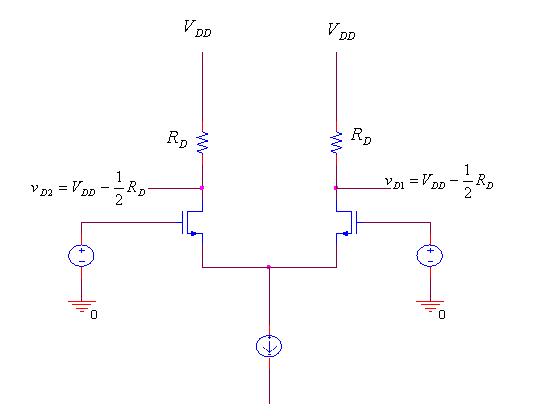
Fig 2.1 The basic MOS differential-pair configuration
through a resistance RD, in most cases active (current-source) loads are employed, as will be seen shortly. For the time being, however, we will explain the essence of the differential pair operation utilizing simple resistive loads. Whatever type of load is used, it is essential that the MOSFETs not enter the triode region of operation.
References
References